Color coding
Hexadecimal
Register/input
Instruction
Internal registers or complicated instructions
Operation
Index
-
- Introduction and specs
- Main differences with R216 and CISC architectures
- Instruction rules
- Instruction encoding
- Instruction set
- All I/O
- Examples
Introduction and specs
First of all, this guide will explain everything you'll need to know while trying to keep it simple and concise, but if you have any question be sure to hit me up on the subframe Discord (i go by DanielUbTb). You can also post questions in the tpt forum, though i check that less frequently.
The Riskete is a 29 bit machine that uses a RISC-V like instruction set.
All the values are numeric values in two's compliment and the lowest bit is in the blue end. The bit 0x20000000 is used to avoid bray anihilation and must always be set.
These are the main features:
-
- 29-bit structure for instructions and aritmetic and logic operations (shifting, adding, logic, comparision).
- 16 29-bit registers. 15 of them usable.
- 4k of 29-bit RAM.
- 29-bit R216 like I/O.
- Buit in debugger for less painfull headaches.
- No flags.
Main differences with R216 and CISC architectures
All of these quirks come from RISC-V, they have a real reason to exist, like lesser instruction length or smaller energy consuption; but I've used a lot of them in the Riskete since they make for super easy and simple hardware . The most important quirks are:
-
- No flags, comparision results are stored in registers as 0x1 or 0x0.
- No addition carries.
- Register 0 is Read-Only, with a value of 0.
- Immediates can only be 15 bit unsigned integers.
- Instructions don´t have operand modes, each instruction uses the data in its own way.
- They will nomally only have one output and two inputs: one register input and a register or Immediate input
- Since there are no flags, conditional branches require comparing two registers (you can compare with register 0 for sign checking).
Instruction rules
Instructions will always have:
-
- The instruction code.
- A register "A", normally used as output register.
- A register "B", normally used as input register.
- Additional data that can be either a register "C" or a 15-bit unsigned immediate value, normally refered to as "X".
Each instruction will use this data in a different way, some of them are:
rA = rB + x
//For all ALU operations

RAM address(rB + x) = rA
//For RAM writing with an offset

bump port(x)
//Some instructions don't use all the inputs
This configuration is explained for each instruction.
Instruction encoding
The encoding of any instruction will always have this format (in hexadecimal):
0xIIABXXXX
Where:
-
- "II" will be the instruction, between 0x20 and 0x3f.
- "A" will be the register A.
- "B" will be the register B, who could have thought.
- "XXXX" will be either a register C or a immediate. This will be determined with the bit 0x8000. If it is a 1 the data will be interpreted as a register. Otherwise it will be interpreted as a immediate.
Instruction set
If you already understand the instructions, here's a small and simple scheme.
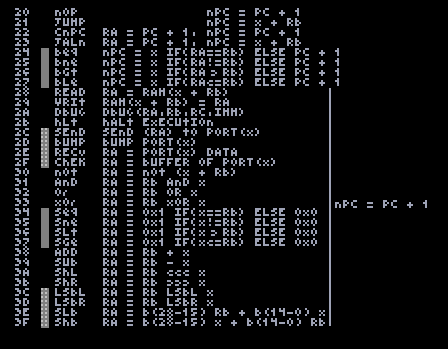
PC is the Program Counter internal register, it points to the instruction that's being executed.
nPC is the value that PC will take in the next frame.
x can be rC or 15-bit Unsigned Immediate
-
-
0x20 NOP "No operation"
- The machine doesn´t do any operation.
- null
- nPC = PC + 1
-
0x21 JUMP
- Goes to the address X + rB.
- null
- nPC = x + rB
-
0x22 CNPC "Copy next PC"
- Copies next address to rA.
- rA = PC + 1
- nPC = PC +1
-
0x23 JALN "Jump and link current PC + 1"
- Like a Jump, but with the added functionality that it stores the PC + 1 in rA.
- rA = PC + 1
- nPC = x + rB
-
0x24 BEQ "Branch if equal"
- A conditonal Jump, it will only branch if rA is equal to rB. Be carefull when writing branches since rA is an input.
- null
- nPC = x IF ( rA == rB ), ELSE PC + 1
-
0x25 BNE "Branch if different / not equal"
- A conditonal Jump, it will only branch if rA is differnt to rB. Be carefull when writing branches since rA is an input.
- null
- nPC = x IF ( rA != rB ), ELSE PC + 1
-
0x26 BGT "Branch if greater than"
- A conditonal Jump, it will only branch if rA is greater than rB. You can make it be a "less than" if you switch the registers. Be carefull when writing branches since rA is an input.
- null
- nPC = x IF ( rA > rB ), ELSE PC + 1
-
0x27 BLE "Branch if less or equal"
- A conditonal Jump, it will only branch if rA is less than or equal to rB.. You can make it be a "bigger or equal" if you switch the registers. Be carefull when writing branches since rA is an input.
- null
- nPC = x IF ( rA <= rB ), ELSE PC + 1
-
0x28 READ "Read the value at address rB + x"
- Reads the value at RAM address rB + x. The x offset can be vey usefull for arrays or stacks.
- rA = RAM address ( x + rB )
- nPC = PC + 1
-
0x29 WRIT "Write a value at address rB + x"
- Sets the value at RAM address rB + x. The x offset can be vey usefull for arrays or stacks.
- RAM address ( x + rB ) = rA
- nPC = PC + 1
-
0x2A DBUG "Prints the values of registers A, B and C; as well as current PC"
- Prints the values of the selected registers, as well as PC. This get printed at the right side of the RAM. Very usefull for debugging.
- debug ( PC, rA, rB, rC )
- nPC = PC + 1
-
0x2B HLT "Halt execution"
- Shuts off the computer completely and resets registers.
- null
- null
-
0x2C SEND "Send register A to Port x"
- Sets the sending flag on the IO to true and sends rA. All of this is only done in that frame.
- send ( rA ) to port ( x )
- nPC = PC + 1
-
0x2D BUMP "Send a bump to Port x"
- Sets the bump flag on the IO to true. All of this is only done in that frame.
- bump port ( x )
- nPC = PC + 1
-
0x2E RECV "Recieve from Port x"
- Sets the recievig flag on the IO to true and sets rA to whats being received. All of this is only done in that frame.
- rA = recieve from port ( x )
- nPC = PC + 1
-
0x2F CHEK "Chek buffer from Port x"
- This is the only instruction that's different form the R216 protocol. Sets the checking flag on the IO to true. This instruction is used to check how many data is buffered and ready to be sent. In the case of R216 peripherals this will be "1" or "0". All of this is only done in that frame.
- rA = recieve from port( x )
- nPC = PC + 1
-
0x30 NOT
- This uses rB + x as input just to have a little bit more flexibility
- rA = not ( x + rB )
- nPC = PC + 1
-
0x31 AND
- Logical and of x and rB
- rA = x and rB
- nPC = PC + 1
-
0x32 OR
- Logical or of x and rB
- rA = rB or x
- nPC = PC + 1
-
0x33 XOR
- Logical xor of x and rB
- rA = x xor rB
- nPC = PC + 1
-
0x34 SEQ "Set if equal"
- If x and rB are equal rA will be set to 0x1, else it will be set to 0x0
- rA = 0x1 IF ( x == rB ), ELSE 0x0
- nPC = PC + 1
-
0x35 SNE "Set if different / not equal"
- If x and rB are different rA will be set to 0x1, else it will be set to 0x0
- rA = 0x1 IF ( x != rB ), ELSE 0x0
- nPC = PC + 1
-
0x36 SLT "Set if less than"
- If x is less than rB rA will be set to 0x1, else it will be set to 0x0
- rA = 0x1 IF ( x < rB ), ELSE 0x0
- nPC = PC + 1
-
0x37 SGE "Set if greater or equal"
- If x is bigger or equal to rB rA will be set to 0x1, else it will be set to 0x0
- rA = 0x1 IF ( x >= rB ), ELSE 0x0
- nPC = PC + 1
-
0x38 ADD
- Adds the values in rB and x in two's compliment. Max positive value is 268435455 or 0xFFFFFFF.
- rA = rB + x
- nPC = PC + 1
-
0x39 SUB "Substract"
- Substracts x from rB in two's compliment. Max positive decimal value is 268435455 or 0xFFFFFFF.
- rA = rB - x
- nPC = PC + 1
-
0x3A SHL "Shift left"
- Shifts bits to the left by the amount stored in the 5 least significant bits of x, the rest are ignored. Also shifting by 31 is the same as 30 and 29, because 29 bit architecture. Shifting with x = 70 is the same as shiting with x = 6 or 134.
- rA = rB <<< x
- nPC = PC + 1
-
0x3B SHR "Shift right"
- Shifts bits to the right by the amount stored in the 5 least significant bits of x, the rest are ignored. Also shifting by 31 is the same as 30 and 29, because 29 bit architecture. Shifting with x = 70 is the same as shiting with x = 6 or 134.
- rA = rB >>> x
- nPC = PC + 1
-
0x3C LSBL "Shift left by LSB"
- Shifts bits to the left to the position of the Least Significant Bit of x. This has the same functionality as "variable red shift".
- rA = rB <<< by LSB of ( x )
- nPC = PC + 1
-
0x3D LSBR "Shift right by LSB"
- Shifts bits to the right to the position of the Least Significant Bit of x. This has the same functionality as "variable blue shift".
- rA = rB >>> by LSB of ( x )
- nPC = PC + 1
-
0x3E SLB "Set low bits"
- Sets rA to the least significant 15 bits of x + the 14 most significant bits of rB. Here's a graphical explanation in binary:
rB = 0b01001011101111111011111100100
x = 0b10001000010011110011110110100
then
rA = 0b01001011101111110011110110100
- rA = bits ( 28 - 15) of ( rB ) + bits ( 14 - 0 ) of ( x )
- nPC = PC + 1
- Sets rA to the least significant 15 bits of x + the 14 most significant bits of rB. Here's a graphical explanation in binary:
-
0x3F SHB "Set high bits"
- Sets rA to the most significant 14 bits of x + the 15 least significant bits of rB. Here's a graphical explanation in binary:
rB = 0b11101111110010101001011101111
x = 0b10011110110100100010000100111
then
rA = 0b10011110110100101001011101111
- rA = bits ( 28 - 15 ) of ( x ) + bits ( 14 - 0 ) of ( rB )
- nPC = PC + 1
- Sets rA to the most significant 14 bits of x + the 15 least significant bits of rB. Here's a graphical explanation in binary:
-
All I/O
The IO protocol was built to use the same protocol as the R216 so if you are familiar with it you'll find no trouble learning it.
IO Protocol explanation
Like I said the functinality of the instructions is the same for SEND, BUMP and RECV. I introduced a new instruction, which is CHEK, and it's different to WAIT. It checks how many messages are buffered in the peripheral, normally one but if you want to make a complex peripheral this can be helpfull.
IO Cables explanation
The computeer sends two signals and receives one. The two outputs are the "control line" and the "output line".
-
- "The output line" The topmost cable is set to the value of rA. It sends a 29-bit signed number, with the 29th bit always being true to avoid BRAY anihilation. This is done always, even when the computer is off or not sending anything. This is definetly safe and not easy to exploit, but i made this decision so that the IO could be a little more flexible.
Also it will send 0x220ff000 if the Riskete isn´t powered on. - "The control line" The second cable is used to send the port and the instruction. Also if the instruction isn't a IO related one it gets set to 0x2dead000 and 0x220ff000 if the Riskete isn´t powered on. If a IO related instruction is being executed this cable will generaly be set to:
0x20000IPP
Where PP is the port and I is:- 0x1 for SEND
- 0x2 for BUMP
- 0x4 for RECV
- 0x8 for CHEK
Though when sending the value of x gets "ored" with 0x20000I00 so if you want to send different data through the control line you can always do that.
- "The input line" Finally the third cable is for sending data to the computer itself. It will be read on RECV and CHEK. This must be a continuous line only interrupted if you want to send data with a DTEC. This must be erased before the next frame so that it can be set from the rightmost end.
- "The output line" The topmost cable is set to the value of rA. It sends a 29-bit signed number, with the 29th bit always being true to avoid BRAY anihilation. This is done always, even when the computer is off or not sending anything. This is definetly safe and not easy to exploit, but i made this decision so that the IO could be a little more flexible.
Examples
Now we get in the nitty-gritty stuf. Here i´ll add some introductory assembly code, like the Fibonacci Sequence and those sorts of stuff; but also specific hacks of this machine. Here are some exaples:
Fibonacci sequence:
load_registers:
SLB r1, r0, 0x1 //Two different ways of loading a register
ADD r2, r0, 0x1
JUMP compute_sequence_and_send

compute_sequence_and_send:
ADD r3, r1, r2
ADD r1, r2, r0
ADD r2, r3, r0
BGT r0, r3, end_of_program //End the program if the result overflows
SEND r3, 0x0 //Send the next to a peripheral to display it
JUMP compute_sequence_and_send

end_of_program:
HLT

//As you can see this is the not the best possible implementation,
//try programing a faster method.