
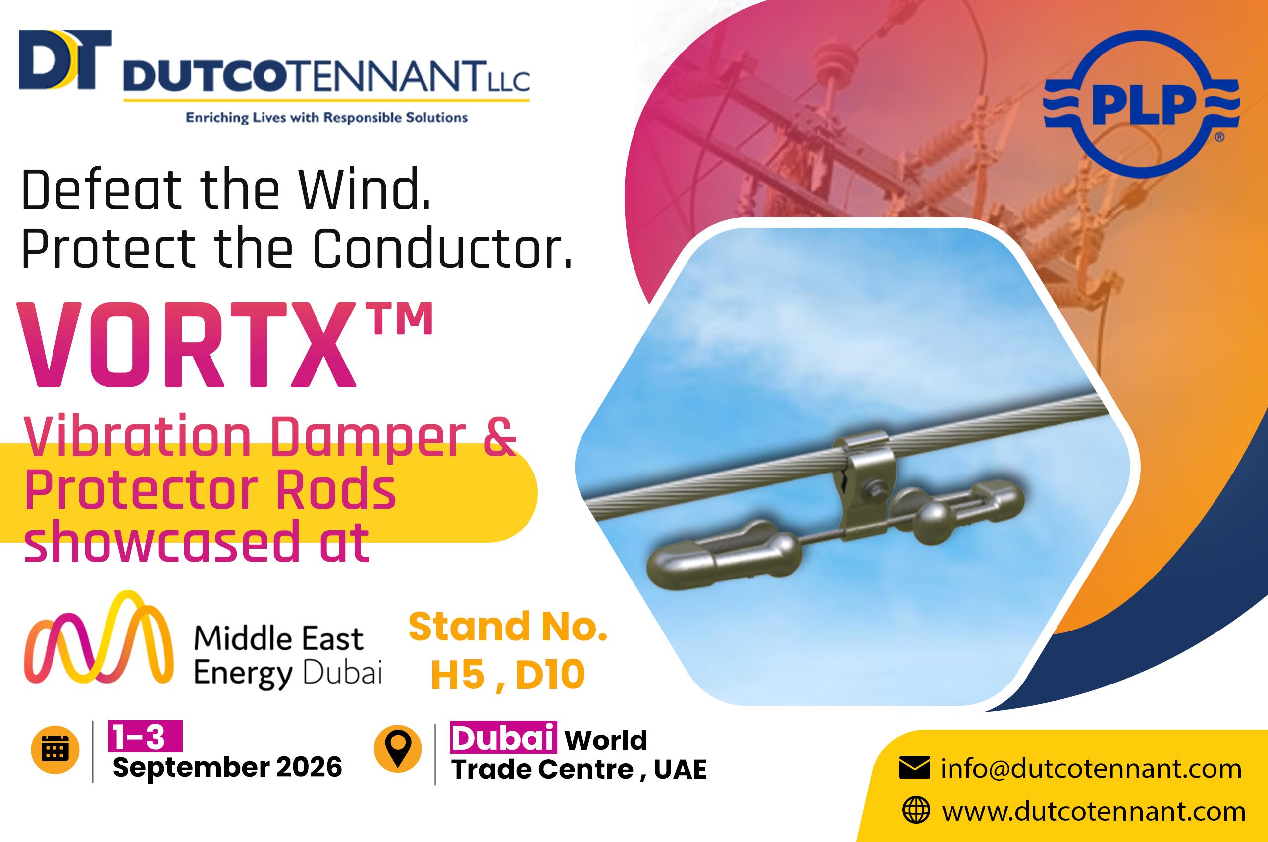
Wind-induced conductor movement can appear modest from ground level while creating repeated dynamic stress near suspension and termination hardware. Over time, high-frequency, low-amplitude aeolian vibration can contribute to fatigue at these concentrated stress zones. Selecting a vibration damper for transmission line use therefore requires more than confirming that a device can be attached to the conductor.
VORTX™ Vibration Damper and Protector Rods form part of a motion-control approach for overhead conductors and cables. Their effectiveness depends on the vibration mechanism, conductor characteristics, damper response, placement and the interface between the clamp and the line. These five checks provide a practical way to evaluate the system before procurement.
1. Confirm the motion that needs control
Aeolian vibration is associated with relatively high-frequency, low-amplitude conductor motion caused by wind. It differs from larger-amplitude line movements, so the first task is to identify the behaviour being addressed rather than applying one motion-control product to every wind exposure.
The evaluation should use conductor or cable type, diameter, mass, tension, span length, support arrangement and terrain information. Operating history can add useful evidence, including visible strand wear, damaged accessories or repeated findings near supports. A conductor vibration damper should then be assessed against the expected frequency range and the dynamic stresses at the attachment points.
2. Look beyond a single response frequency
The VORTX vibration damper design uses large and small damper weights. The two weight sizes provide up to four resonant response frequencies, with the smaller weight contributing damping at higher frequencies. This wider response range helps dissipate energy across more of the conductor or cable's vibration spectrum than a symmetrical-weight arrangement.
Conductor size influences this review. Larger conductors generally vibrate at lower frequencies, while smaller-diameter cables can respond at higher frequencies. The selected weight combination and clamp range must therefore correspond to the line being assessed. An overhead line vibration damper should not be transferred from one conductor schedule to another solely because the hardware looks similar.
Published configurations are available for several aluminium-based conductors, including ACSR, AAC, AAAC, ACSS and ACAR. The applicable catalogue entry remains dependent on the exact diameter and construction. For relevant configurations, a continuous thermal rating up to 250°C is published, subject to the correct installation interface and product selection.
3. Decide when Protector Rods belong under the clamp
Protector Rods add a layer of mechanical protection and reinforcement where an accessory such as a damper clamps onto a conductor or cable. They reduce direct clamping stress on constructions that may be vulnerable to surface or core damage. Their need varies with conductor design, attachment location and the protective rods already present at nearby support hardware.
Their purpose has clear limits. The rods are not repair products and are not intended to restore conductance or tensile strength. They are also not designed as protection at clamp-type supports or suspensions. This distinction prevents a clamping-interface accessory from being specified as a general conductor repair or support solution.
Standard versions are designed for line voltages of 230 kV and below, while suitable end treatment can be provided for higher-voltage applications. Selection is tied to cable or conductor diameter, rod length, rod diameter and colour code. Where the damper is installed over the rods, the clamp range must account for the increased overall diameter.
4. Treat placement as a span-specific calculation
Damper quantity and position should reflect the line and terrain conditions rather than a repeated distance copied across the route. Placement methods use laboratory performance data together with standing-wave geometry for critical wind velocities. Long spans, dead-end-to-dead-end spans and changes in support arrangement may require a different position or a protective rod set beneath the clamp.
A useful placement submission should state the conductor or cable data, span lengths, tensions, support hardware, terrain category and relevant environmental assumptions. It should also show whether the damper sits on existing suspension rods, on the bare conductor or on a separately protected section. These details allow reviewers to understand the load interface instead of seeing only a damper count on the bill of materials.
This is where an evaluated placement recommendation adds lifecycle value. Correct positioning targets the standing-wave pattern being controlled and creates a repeatable basis for installation checks along the route.
5. Make installation records part of the design
The clamp and keeper secure the damper to the conductor or cable, while the messenger and unequal weights provide the dynamic response. Product identification, installation torque and lot information are permanently marked on the clamp. An optional break-away bolt arrangement is also available for applicable configurations.
Receipt inspection should verify the catalogue number, weight combination, clamp range, bolt option and any Protector Rod set before materials are issued. Field records should capture the structure reference, span, installed position and completion check. This makes later inspection far more useful because teams can compare the in-service assembly with the approved placement schedule.
The product has published compliance with IEC 61897 for Stockbridge-type aeolian vibration dampers. Project specifications should still define the required evidence, application procedure and acceptance records instead of relying on a general standards reference alone.
Use inspection findings to keep the model current
After commissioning, inspection should cover clamp security, messenger condition, weight integrity, Protector Rod position and visible conductor distress. Findings at repeated structures may indicate a local installation issue, while patterns across several spans may justify a fresh vibration or placement review.
Any change in conductor tension, span geometry, support hardware or operating temperature should trigger a compatibility check. Effective damping comes from keeping the original design inputs, field installation and later operating conditions connected throughout the asset record.
Continue the evaluation at Middle East Energy 2026
Middle East Energy 2026 will take place from 1 to 3 September at Dubai World Trade Centre, UAE. The exhibition gives engineers, utility teams, contractors and procurement specialists an opportunity to compare motion-control approaches against actual conductor and route data while exploring Power distribution solutions at Middle East Energy.
Visitors seeking a closer look at VORTX™ Vibration Damper and Protector Rods can find Dutco Tennant at Stall H5, D10. Bringing the conductor datasheet, span schedule, tensions, support arrangement and terrain information will help the conversation move from a general product review to a more useful placement and interface discussion with an experienced Transmission Equipment Supplier in MEE Dubai.
An effective evaluation follows the vibration path from wind input to conductor response, damper frequency range, clamp interface and field placement. Keeping those decisions traceable helps protect the conductor and gives maintenance teams a stronger baseline for future inspections, supporting coordination with an Electrical Connectors Supplier in MEE 2026.