
Understanding Bearing Radial and Axial Loads
Bearings play an important role in machinery operation by supporting shafts and guiding, rotating, or oscillating around shafts while minimizing friction. To ensure the optimal performance and life of machinery components you must understand the forces affecting bearings as either pure radial, pure axial, or a combined radial and axial load.
Radial loads act perpendicular to the shaft. Most standard single-row radial bearings are selected for their use in applications that have primarily radial loads.
Axial loads act parallel to the shaft’s axis. Thrust bearings are selected for applications with only axial loads.
It is essential to consult with your supplier or look up the load ratings in manufacturers catalogs to determine the most suitable bearing. Accurate calculations of these forces are essential in choosing the right bearing type and ensuring its efficiency and life.
- Dynamic Load Capacity is defined as the constant stationary radial load in which a rolling bearing can theoretically last with a basic rating life of one million revolutions.
- Static Load Capacity: Shown in manufacturers catalogs as the maximum load a bearing can withstand without any permanent deformation while stationary. Exceeding the manufacturers catalog specifications may lead to material fatigue and eventual bearing failure. This specification is typically designated as the symbol C0 and is measured in units of force, such as Newtons (N).
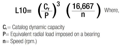
A basic fatigue life rating known as L10 is a bearing’s basic fatigue life rating and is calculated using the number of rotations in which 90% of all bearings in a specific group achieve or exceed a calculated time without failure (probability of failure: 10%).
Find your bearing’s dynamic capacity in the catalog, estimate the radial load, and RPM, and you are able to calculate your own L10 bearing life. The L10 life calculation indicates the life of the bearing in your operating conditions with 90% accuracy.
Therefore, loads are normally obtained by multiplying theoretical values with various coefficients developed over time.
There is a lot of math involved, but you can find this information on many manufacturers’ sites.
The Computation of Bearing Loads is simplified as follows:
- R= Radial load – loads that are perpendicular to the shaft
- T= Thrust load – loads that are parallel to the axis of the bearing
- C= Combined load is a result of calculating both Radial and Thrust loads using the combined load calculations
To calculate dynamic equivalent radial load (composed of both radial and axial forces) for a single row deep groove ball bearing is as follows:
P=XFr+YFa
- P=Dynamic equivalent radial load
- Fr=Radial load
- Fa=Thrust load
- Z= number of balls
- D= ball diameter
- X=Radial load factor
- Y=Thrust load factor
- e=Limiting factor for Fa/Fr
The static equivalent radial load on single-row deep groove bearings subject to both radial and axial (thrust) loads is computed as follows:
Po=0.6 Fr +0.5 Fa
- Po=Static equivalent load
- Fr=Radial load
- Fa=Axial load

Common Sources of Loads are:
-
- Weight- shafts, gears, pulleys, or other machine parts supported by bearings
- Centrifugal Force – out of balance conditions-eccentrics, or as in wheel bearings while turning curves
- Tension – required to transmit power as in timing or drive beltsTorque Reaction – producing loads due to the twisting effect of power input, on bearings supporting drive pinion or worm gear, etc.
Power transmission losses are present depending upon the efficiencies of the elements involved. However, in the methods of calculations, the efficiency of 100% is used in order to keep the solutions as simple and direct as possible.
Contact Us for further assistance.