Some of the home appliances company use different time long, there will inevitably be some components aging lead to system circuit design can not meet the normal management work, but the enterprise if a circuit is bad we throw away a little too much waste of human resources, it is not allowed to say that the circuit of a component in the aging, if you need to be able to find the faulty components replaced by ourselves, we can save a fortune, and at the same time learn some techniques to detect faulty circuits. At the same time also learned some skills.
Today we will teach you a simple multimeter to determine if a component is burnt and should not be replacedhow to test pcb board with a multimeter.
Capacitor Detection
Step 1: Set your multimeter to capacitance and select the appropriate setting.
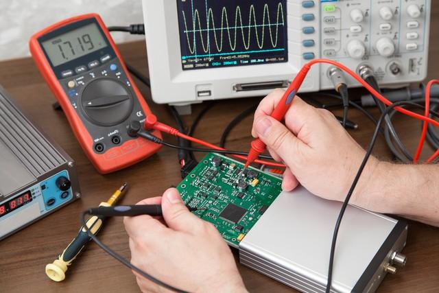
Step 2: Place the pens on the multimeter on the pins at the ends of the two components
We can clearly see that the small capacitance is measured with an indicator, read the indicator displayed on the multimeter, and then compare the actual value labeled on the capacitor. If the two values are close, the capacitor is normal. Our capacitor is labeled 10uf and the actual measured value of 13.8uf can be considered close.
Then look at the second picture, you can get a very obvious to see the multimeter signal directly to zero, which also needs to be enough to show that the enterprise this drum capacitance is really burned,1oz vs 2oz Copper if you want to go through the restoration technology to find an important parameters are the same as the capacitance to replace this one.
Diode detection
Speaking of capacitors, let's talk about diode detection. Diode detection method than the capacitance detection method is a little simpler, because our multimeter has its own diode module, there is only one position, regardless of the size of the range, we have switched to the diode to stop, and then the positive end of the multimeter is connected to the diode's anode, the negative end of the multimeter is connected to the diode's positive pole, if you see a number on the display of the multimeter, the diode in the circuit is working (some multimeters will ring) and is not worn out.
Inductance Test
Inductance is a very important component in a cell phone charger, and almost every charger has an inductor. Therefore, it is necessary to learn a way to detect inductance. "Inductance" was learned in high school. Inductance is equivalent to a short circuit to DC, and we can make good use of this in combination with the diode block on the multimeter.
It is well known that if you connect the red and black diode block meter directly to the multimeter, it will make a sound. Instead of connecting it to the multimeter, connect it to the inductor and try it out. Note that, in addition to the fact that the buzzer does not sound, before the multimeter is connected, only a diode symbol is displayed in the upper right corner.
Next we connect the multimeter to both sides of the inductor and watch the change on the display in the upper right corner of the multimeter display.
Is not another with a similar to the Chinese cell phone for signaling the kind of symbols, it is to express the meaning of the inductor is normal without a circuit breaker, out of the social phenomenon of this problem at this time you will also hear the buzzer sounded, this time we need to be able to determine the inductor is normal.
Related articles:
How do I use a multimeter to conduct a continuity test on an electrical component?
How to check circuit faults with a multimeter? How to troubleshoot circuit fault