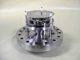
A microchannel plate (MCP) is a quick high-gain electron amplifier with numerous parallel spatial channels that can be used in imaging applications. It is directly sensitive not only to input electrons but also to other charged particles (such as ions or elementary particles) and electromagnetic radiation with a suitably short wavelength (high photon energy), i.e., from the ultraviolet to the visible spectrum. The kind and energy of the particles or photons have a big impact on detection efficiency (quantum efficiency). A photocathode in front of the MCP can be used to achieve sensitivity to visible or infrared light.
MCPs are found in a variety of photonic devices, including image intensifiers and image converters. In addition, they are used to detect X-rays in medical diagnostics and for industrial inspection. Time-of-flight mass spectrometry, nuclear physics, other fundamental physics, and electron microscopy are some of the other applications.
Microchannel Plates: Principles of Construction and Operation
A is essentially a plate (disc) with a thickness of, say, 1 mm, made of an electrically insulating substance (usually glass) and a hexagonal grid of microscopic holes (see Figure 1 a). In most cases, the front and back faces are either circular or rectangular microchannel The active area's diameter can be as little as 20 mm, as large as 50 mm, or as large as 100 mm. Each channel can have a diameter of 10 m or 20 m, for example.
MCPs can be made using the following method, for example:
Many glass fibres are bundled together and fused at a high temperature.
One cuts a slice against the fibre axes from the fused bundle at a bias angle (see below).
The fibres feature a material fibre core that may be scratched away to reveal the pattern of holes (the channels).
A thin semiconductor layer is formed on the channel walls after a chemical treatment. That layer is designed to have a high secondary electron emission efficiency while also having a low electrical conductivity.
To make electrodes, a thin metal coating, usually, a nickel alloy is vaporised onto the end faces. Those electrodes pierce the channels a little.
During operation, the electrodes are exposed to an electric voltage of the order of 1 kV.
Electrons strike one side of the microchannel plate, which are generated, for example, in a photocathode 1 mm distant from the plate. Typically, the setup is made so that the electron paths have a minor bias angle (on the order of 10°) against the channel axes.
A single electron with sufficient energy (e.g. a few hundred electron volts) delivered onto the input side can generate several secondary electrons, which can then hit the channel's inner side and generate more electrons. The resultant electron avalanche can create thousands of output electrons after several such cycles. Each of the several channels can function as a stand-alone electron amplifier. On the other side, the spatial distribution of output electrons roughly mimics that of incoming electrons.
Due to the non-zero conductivity of the plate material, there is still some weak strip current even without any input electrons. While a low strip current may be preferable in terms of power consumption, larger values are preferable in terms of reliability. MCPs are frequently used in analogue mode, with the output signal roughly proportional to the input signal. However, they can also be used in counting mode, which counts input events without taking into account the electric charge per count: every event with a charge above a certain threshold is counted.
MCPs' Most Important Characteristics
Using a combination of MCPs
A combination of two or three microchannel plates, placed face to face (but not with alignment for the apertures) and electrically coupled in series, is sometimes used to get a particularly high again (without metallic coatings at the interfaces between the plates). The performance can be significantly greater than utilising a single microchannel plate with proportionately longer channels because positive ions moving backwards are usually halted at the interfaces between the plates. As a result, a larger gain can be achieved without excessive noise.
There is some loss of spatial resolution because the channels of the successive plates are often not aligned: electrons from one channel can enter into more than one channel of the following plate at an interface.
Incorporated into an Image Intensifier
A photocathode generates photoelectrons in an image intensifier, which are driven towards the microchannel plate by an electrical voltage of, say, 400 V. Because of the narrow distance between the photocathode in the input side of the microchannel plate (e.g. 2 mm), proximity coupling occurs, in which each photoelectron is most likely to enter the ch closest to it.
The plate's output electrons can then be routed to a phosphor screen (with additional acceleration, such as many kilovolts) to form a visible image, such as for direct eye viewing. Alternatively, the electrons could be sent to an electronic sensor. An image intensifier like this could be used as a kind of preamplifier for a camera, such as a CCD camera.
Microchannel Photomultiplier Application
The spatial resolution is not always required. A tiny photomultiplier can be built in the same way as an image amplifier, with a photocathode in front of a microchannel plate and a single electrode receiving all output electrons. Between the MCP output and the anode, a modest voltage, such as 100 V, is applied. The entire detector can be housed in a cylindrical housing that is only a few centimetres in diameter and length. A single high voltage is normally obtained by the device, which is then internally spread over the three components using a simple voltage divider (made with resistors).

