Introduction
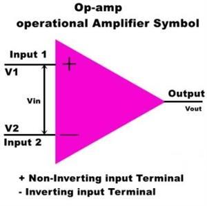
An operational amplifier or op-amp is used in a wide variety of applications in electronics. It generally comprises a differential-input stage with high input impedance, an intermediate-gain stage, and a push-pull output stage with a low output impedance. Common operational amplifier has two input pins and one output pin. Its basic role is to amplify and output the voltage difference between the two input pins. So it is pretty common in electronic as an analog circuit block. And this note tells you the most commonly used op-amps and how to choose an op-amp for your circuit requirements.

1 How Does An Op-Amp Work?
An op-amp is a multi-stage, direct-coupled, high gain negative feedback amplifier. It is basically a three-terminal device which consists of two high impedance inputs. Ideally, it only amplifies the difference in voltage between the two, also called differential input voltage. Op-amps are still a primary building block for analog systems, performing tasks like amplification, active filtering, and signal transformation. In digital systems, op-amps are used in buffers, analog-to-digital converters, digital-to-analog converters, and regulated power supplies, to name a few applications.
2 Understanding Basic Op-amp Parameters
Op-amps are linear devices that are ideal for DC amplification and are used often in signal conditioning, filtering or other mathematical operations. So understanding its basic parameters is important to employ it well in circuits.
2.1 What are the Parameters of Op-Amp?
Gain Bandwidth
1) Gain bandwidth product: Due to parasitic junction capacitance and minority-carrier change storage in devices, the voltage gain of op-amp decreases at high frequencies, it refers to the bandwidth and gain product.
2) Unity gain bandwidth: As the input signal of the frequency increases, the open-loop gain drops off until it finally reacts to the value 1. The frequency at which the gain reduces to 1 is defined as unity gain frequency or unity-gain bandwidth.
Input Offset Voltage
It is a very small voltage applied at the outputs, to make the output terminal zero of the operational amplifier. It reflects the symmetry of the op-amp circuit. The better the symmetry, the smaller the input offset voltage.
Input Offset Voltage Drift
The input offset voltage drift is also called the temperature coefficient. In a given temperature range, it is the ratio of the change in the input offset voltage to the temperature change. This parameter is actually a supplement to the input offset voltage. Within a given operating range, the magnitude of the drift of the amplifying circuit depends on the temperature changes.
Input Bias Current
When the output current-voltage of the op-amp is zero, input bias current refers to the average value of the bias current of the two input terminals that flows into the inverting and non-inverting input terminals of the Op-Amp. It has a greater impact on the places where the input impedance is required, and it is generally related to the manufacturing process. The smaller the input bias current the smaller the drift.
Input Offset Current
When the output current-voltage of the op-amp is zero, the input offset current means the difference between the bias currents of the two input terminals. It also reflects the symmetry of the circuit inside the op-amp. The better the symmetry, the smaller the input offset current.
Input Resistance
1) Differential mode input impedance: when the operational amplifier is working in the linear region, it is the ratio of the voltage change at the two input terminals to the corresponding current change. It includes input resistance and input capacitance and only refers to input resistance at low frequencies.
2) Common-mode input impedance: It is the ratio of the input current change when the op-amp is inputting a signal (that is, the same signal is input at the two input terminals of the op-amp). At low frequencies, it appears as a common-mode resistance.
Output Resistance
When the operational amplifier works in the linear region, a voltage signal is added to the output terminal of the operational amplifier, output resistance means the ratio of the voltage change to the corresponding current change. At low frequencies, it only refers to the output resistance of the op-amp. This parameter needs to be tested in an open-loop state.
Voltage Gain
1) Open-loop gain: the amplification factor of the op-amp without negative feedback (in the open-loop state). The ideal value is infinite, generally about thousands to tens of thousands of times, and it represents by dB and V/mV.
2) Closed-loop gain: in the case of negative feedback, it refers to the amplifier magnification.
Voltage Swing
When the op-amp is working in the linear region, voltage swing is the maximum voltage amplitude that the op-amp can output under the specified load and the current power supply voltage.
Input Voltage Range
1) Differential mode input voltage range: The maximum differential mode input voltage is defined as the maximum allowable input voltage difference between the two input terminals of the operational amplifier. When the input voltage difference of the op-amp exceeds it, the input stage of the op-amp may be damaged.
Common mode belongs to the rabbit voltage range: when the operational amplifier is working in the linear region when the common-mode rejection ratio of the operational amplifier deteriorates significantly is the maximum common-mode input voltage. It limits the maximum common-mode input range in the input signal, therefore, special attention is required in the case of interference.
Slew Rate
The slew rate of the op-amp is defined as the input of a large signal (including a step signal) to the input under the closed-loop condition. It indicates how fast the output of OP-AMP can change in response to a change in input frequency. The output rise rate of the op-amp is measured from the output of the op-amp. Since the op-amp is in a closed-loop state during conversion, the feedback loop of the op-amp does not work, that is to say, the slew rate has nothing to do with the closed-loop gain.
CMRR
The Common Mode Rejection Ratio (CMRR) is defined as the ratio of the differential voltage gain to the common-mode voltage gain.
Unity Gain
A Unity gain amplifier is an amplifier that has a gain of 1 that also means there is no gain. The output voltage will be the same as the input voltage it is commonly known as a voltage follower amplifier.
Common Mode Rejection Ratio
When the op-amp works in the linear region, it means the ratio of the differential mode gain of the op-amp to the common-mode gain. It is an extremely important indicator, it suppresses differential mode interference signals. Since the common-mode rejection ratio is very large, the common-mode rejection ratio of most op-amps is recorded and compared in decibels.
Supply Voltage Common Mode Rejection Ratio
When the op-amp works in the linear region, it means the input offset current of the op-amp varies with the supply voltage. Supply voltage common-mode rejection ratio reflects the impact of power supply changes on the output of the op-amp. Pay special attention when used for DC signals or small signals.
Equivalent Input Voltage
A well-shielded op-amp without signal input, any AC interference voltage generated at its output end, when this noise is converted to the input of the op-amp, it is called the input noise voltage (sometimes also expressed by noise current).
2.2 Questions about Op-Amp Important Parameters
1) Why do op-amps need negative voltage?
Op-amps themselves don't have a 0V connection but their design assumes the typical signals will be more towards the centre of their positive and negative supplies. Thus, if your input voltage is right at one extreme or forces the output toward one supply, chances are it won't work properly.
2) Why op-amp has high gain?
The gain of an op-amp represents how much greater in magnitude its output will be than its input, hence its amplification factor. This is usually defined as an open-loop gain or large signal voltage gain.
3) Why Positive feedback is not used in op-amp?
In an op-amp circuit with no feedback, there is no corrective mechanism, and the output voltage will saturate with the tiniest amount of differential voltage applied between the inputs.
4) What is CMRR?
The Common Mode Rejection Ratio (CMRR) is defined as the ratio of the differential voltage gain to the common-mode voltage gain. CMRR is infinity.
5) Why CMRR should be high?
A high CMRR is required when a differential signal must be amplified in the presence of a possibly large common-mode input, such as strong electromagnetic interference (EMI). An example is an audio transmission over the balanced line in sound reinforcement or recording.
6) What is the maximum gain of an op-amp?
The maximum gain is the open-loop gain. It depends on the opamp model and can go anywhere from 60 dB to 120 dB voltage gain. The open-loop bandwidth is however very small. Another issue is that this gain is very variable between different parts of the same product number due to variations.
7) What is the slew rate of an op-amp?
Slew rate (SR) is the maximum rate of voltage change that can be generated by the op-amp's output circuitry. It is measured as a voltage relative to time, and the typical unit used in datasheets is volts per microsecond (V/µs). SR is infinity, which means the ideal op-amp will produce a change in the output instantly in response to an input step voltage.
8) What is the bandwidth of an operational amplifier?
The operational amplifiers bandwidth is the frequency range over which the voltage gain of the amplifier is above 70.7% or -3dB (where 0dB is the maximum) of its maximum output value as shown below.
9) Is higher slew rate better?
Higher slew rates are not always better: Higher slew rate makes for higher operating current. This means higher power consumption. Faster slew rate will make higher bandwidth.

3 Common Op-amp ICs Datasheet Overview
LM741
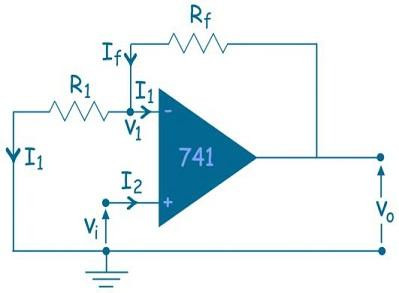
The LM741 series are general-purpose operational amplifiers which feature improved performance over industry standards like the LM709. It is intended for a wide range of analog applications. It has only one op-amp inside. An operational amplifier IC is used as a comparator which compares the two signal, the inverting and non-inverting signal.
* List 1: LM741 Specifications
Max supply voltage: ±22 V
Voltage gain: 200V/mV
Max input voltage: ±15 V
Built-in output short circuit protection
Max output short circuit current is 40 mA.
Input resistance: 6M
Max low offset voltage of 6mv and can drift 15 µV/°C
Applications include a comparator, dc amplifier, summing amplifier, integrator or differentiators and active Filters.
Max input offset current of 70nA and can drift up-to 0.5 nA/°C.
Max Bandwidth is 1.5Mhz;
Max Slew rate is 0.7 V/us.
Max CMRR is 90 dB.
Similar Products: UA741, µA741
Max peak output voltage swing is 16V
Operating temperature range –50 to 125 °C
LM709 Series
The LM709 series is a monolithic operational amplifier intended for general-purpose applications. The precursor to the popular LM741 is the LM709. The 709 had no internal frequency compensation, unlike the 741. Frequency compensation is used to purposely limit an operator's bandwidth. As the input frequency increases, the operator's phase shift also increases. This can contribute to unnecessary oscillation, as an unintended phase-shift oscillator forms the feedback network.
*List 2: LM709 Specifications
Max supply voltage: ±18V
Input resistance: 750K
Max input voltage: ±10V
Output resistance: 150Ω
Max low offset voltage of 6mv and can drift 6 µV/°C
The application includes voltage follower, basic comparator, multivibrator and frequency generator.
Max input offset current of 500nA and can drift up-to 22.8 nA/°C
Package: TO-5, Pin Nb=8
Max CMRR is 70dB.
Similar parts: OP77, UA70
Peak output voltage swing is 24V
Operating temperature range –55 to 125 °C
LM1458
LM1458 is a dual general-purpose Operational Amplifier (Op-amp). Its has two built-in amplifiers having a common power supply, and short circuits protected and require no external components for frequency.
*List 3: LM1458 Specifications
Max supply voltage: ±18 V
Input resistance: 1MΩ
Max input voltage: ±15V
Max CMRR is 90dB
Voltage gain: 15V/mV
Built-in output short circuit protection
Max low offset voltage of 6mv and can drift 15 µV/°C
Input offset current of 300nA max and can drift up-to 0.5 nA/°C
Max peak output voltage swing is 14V.
Max bandwidth is 1MHz.
Operating temperature range 0 to 70 °C
Applications include summing amplifiers, portable devices, comparators, integrators, etc.
Similar Products: MC1458
Packages have TO-CAN, DSBGA, SOIC and PDIP.
LM324
The LM324 series are low−cost, quad operational amplifiers with true differential inputs. They have several distinct advantages over standard op-amps. It is a single supply, high gain, internally frequency compensated quad op-amp. And it can be operated from a single or split power supplies.
*List 4: LM1324 Specifications
Max supply voltage: 32 V
Output resistance: 350Ω
Voltage gain: 100 V/mV
Max output short circuit current is 60 mA
Input bias current: 100nA
Built-in output short circuit protection
Max low offset voltage of 3mv and can drift 30µV/°C
Max input offset current of 30nA and can drift up-to 300 pA/°C
Max CMRR is 85dB.
Max peak output voltage swing is 16V.
Bandwidth is 1MHz.
Operating temperature range 0 to 70 °C
Packages: 14-pin PDIP, 14-pin CDIP, 14-pin SOIC, and 14-pin TSSOP
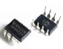
NE5532
Compared to the standard dual op amps, the NE5532 is a Dual Low Noise Op-Amp in 8-pin package commonly used as amplifiers in audio circuits for its noise immunity and high output drive capability. The Op-Amp is internally compensated for high unity gain with maximum output swing bandwidth, low distortion and high slew rate.
*List 5: NE5532 Specifications
Max supply voltage: ± 15V
Input bias current: 1000nA
Max supply current: 10mA
Low offset voltage: 5 mV
Input offset current: 200nA
Built-in output short circuit protection
Max output short circuit current is 60 mA
Input resistance: 300KΩ
Max CMRR is 100dB.
Output resistance: 0.3Ω
Max peak output voltage swing is 26V.
Max bandwidth is 10Mhz.
Max slew rate is 9 V/us.
Operating temperature range -65 to 150 °C
Applications include Av Receivers, Audio mixer, High-performance audio preamplifier and many more.
4 Conclusion
Op-amps are used in a wide variety of applications in electronics. Some of the more common applications are: as a voltage follower, selective inversion circuit, a current-to-voltage converter, active rectifier, integrator, a whole wide variety of filters, and a voltage comparator. Based on your circuit requirements, you should check out datasheets of different op-amps and select one.

